
Walk through most industrial facilities and you will find pumps and fans running flat out, all day, with a valve or damper throttled halfway shut to bring flow down to what the process actually needs. The motor is still drawing close to full power. The excess is being burned off as wasted heat and noise across that throttled valve, not saved. This single, common setup is one of the most consistent sources of avoidable energy waste in industry, and it has a well understood fix: slow the motor down instead of throttling the output.
This article explains the physics behind why that fix works so well, what a variable frequency drive actually does, and where it pays off fastest.
1. The Affinity Laws: Why Speed Changes Everything
Centrifugal pumps and fans follow a well established set of relationships called the affinity laws, which describe exactly how flow, pressure, and power change as motor speed changes. Flow scales directly with speed, run a pump at 80 percent speed and it moves roughly 80 percent of the flow. Pressure, or head, scales with the square of speed, so at 80 percent speed, head drops to about 64 percent. Power is where it gets interesting: power scales with the cube of speed.
That cubic relationship is the entire economic case for variable frequency drives on pumps and fans.
2. The Cube Law in Plain Numbers
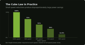
Because power follows the cube of speed rather than a straight line, small reductions in speed produce disproportionately large reductions in power draw:
| Speed | Flow | Power Required | Energy Saved |
|---|---|---|---|
| 100% | 100% | 100% | 0% |
| 90% | 90% | 73% | 27% |
| 80% | 80% | 51% | 49% |
| 70% | 70% | 34% | 66% |
| 50% | 50% | 12.5% | 87.5% |
A 20 percent reduction in speed, something a facility can barely notice on the process side, cuts power draw by close to half. This is why even modest, safe speed reductions on an oversized or underloaded pump or fan translate into large, measurable energy savings.
3. Why Throttling a Valve Wastes What a VFD Would Save
The traditional way to reduce flow on a fixed-speed pump or fan is to throttle a valve or damper, forcing the system to work against additional resistance. The motor keeps spinning at full speed, drawing close to full power, while the throttled valve simply converts the excess energy into heat, turbulence, and noise instead of useful flow. A variable frequency drive achieves the same reduced flow by slowing the motor itself, capturing the cube-law saving directly instead of generating and then discarding energy the process never needed in the first place.
4. Where This Matters Most: Oversized and Underloaded Equipment
VFDs deliver their biggest wins on equipment that was oversized at the design stage, a common and often deliberate safety margin, or on processes where demand varies significantly across a shift, day, or season. A pump sized for peak flow that spends most of its operating life meeting a lower, average demand is exactly the scenario where cube-law savings are largest, since the motor is running well above the speed the process actually requires most of the time.
A concrete example: A 100 HP pump running continuously at full speed in a system that only needs 80 percent of that flow is consuming 100 HP when it could be consuming roughly 51 HP at 80 percent speed, a difference that runs every hour the pump operates.
5. The Catch: Static Head Systems Save Less
The full cube-law benefit applies best to systems dominated by friction, where resistance rises smoothly with flow, closely following the affinity curve. Systems with significant static head, lifting water to a fixed height, for example, behave differently: the pump cannot slow down as much before it stops delivering flow at all, since a portion of the pressure requirement does not fall away with reduced speed. Real-world savings in these systems are still meaningful, but genuinely smaller than the idealized cube-law numbers suggest, and system-specific analysis matters more here than in a purely friction-dominated line.
6. Minimum Speed Limits Are a Real Constraint
VFDs cannot simply be run down to near-zero speed and still deliver useful, reliable performance. Most engineers limit pump and fan speed control to roughly a 30 to 100 percent range as a conservative guideline, since efficiency drops meaningfully below that threshold and mechanical issues, including inadequate bearing lubrication and cooling on motors that rely on shaft-driven fans, can arise at very low speeds. Sizing a VFD retrofit correctly means understanding the actual operating range the process needs, not assuming unlimited turndown is available or advisable.
7. Not Every Load Benefits Equally
The dramatic cube-law savings described above apply specifically to variable-torque loads, centrifugal pumps and fans, where torque requirement drops as speed drops. Constant-torque loads, such as conveyors or certain positive-displacement equipment, do not follow the same relationship, and a VFD on this type of load saves energy through better process control and reduced mechanical wear rather than the same steep power reduction curve. Knowing which category a given piece of equipment falls into is the first real step in estimating whether a VFD retrofit will pay back quickly or modestly.
8. Where VFDs Pay Off Fastest
Pumps and fans running continuously against a throttled valve or damper are the clearest, fastest-payback candidates, since the wasted energy is happening every hour of operation with no offsetting benefit. HVAC fan systems serving variable occupancy or process cooling loads are close behind, since demand naturally varies across a day and a VFD lets the fan track that demand instead of running at a single fixed speed regardless of need. Compressor loading, covered in more depth in our piece on compressed air leaks, is a related but distinct case, since compressor VFD retrofits interact with system pressure control rather than pure flow reduction in the same way pumps and fans do.
9. The Hidden Side Effect: Bearing Currents and Insulation Stress

A VFD does not deliver power to a motor the way utility mains does. It switches DC bus voltage on and off at high frequency to synthesize an approximate sine wave, a technique called pulse width modulation, and that switching produces fast-rising voltage edges, commonly referred to as dV/dt. These sharp voltage transitions create a parasitic common-mode voltage on the motor shaft, which, on larger motors and longer cable runs in particular, can discharge through the bearings rather than through a proper ground path. Over time, this bearing current causes a specific, recognizable damage pattern, small pits and fluting on the bearing races, that is frequently misdiagnosed as ordinary lubrication failure or mechanical wear rather than traced back to the drive.
This is a genuinely different failure mechanism from the electrical harmonics a VFD can inject back onto the supply side, and it does not show up immediately. A motor can run for months before bearing damage from this cause becomes audible or measurable, which is exactly why VFD retrofits on larger motors, generally above 100 HP, and on installations with long cable runs between drive and motor, deserve deliberate attention to this issue rather than treating the retrofit as “just wire the drive to the motor and go.”
How This Gets Mitigated in Practice
None of this is a reason to avoid VFDs, it is a well understood problem with well established fixes, and most are inexpensive relative to the motor and drive themselves:
- Shaft grounding rings provide a low-impedance path for shaft current to reach the motor frame instead of passing through the bearing, and are generally the most cost-effective fix for motors below roughly 100 HP.
- Insulated bearings on the non-drive end block the current path entirely on larger motors, and are frequently combined with a grounding ring for full protection.
- dV/dt or sine wave output filters slow the rate of voltage rise leaving the drive, reducing peak voltage stress at the motor terminals, particularly important on longer cable runs where reflected wave effects are more pronounced.
- Lowering the drive’s carrier switching frequency reduces bearing current magnitude directly, at the modest cost of slightly more audible motor noise.
- Inverter-duty rated motors, built with heavier insulation specifically to tolerate VFD switching stress, remove much of this risk at the source when a motor is being replaced or specified new rather than retrofitted.
The practical takeaway for a facility considering a VFD retrofit on an older, non-inverter-duty motor: this is a solvable, well-documented issue, but it is worth solving deliberately at the point of installation rather than discovering it as an unexplained pattern of early bearing failures a year later.
10. Working Out Whether a VFD Actually Pays Back Quickly
The cube law makes the savings potential clear, but turning that into a real payback estimate requires a few more inputs specific to the equipment in question. The basic calculation looks at three things: the motor’s typical operating power before the retrofit, the power draw expected after adding speed control based on the actual duty cycle, and the facility’s cost per unit of electricity.
Consider a 50 HP pump motor currently running at full speed against a partially throttled valve, where the process actually only needs about 80 percent of rated flow most of the time. At 80 percent speed, shaft power falls to roughly 51 percent of full load, meaning a motor drawing close to 37 kW at full output would draw closer to 19 kW at the reduced, correctly matched speed. Running continuously across a year, that difference alone, multiplied by the facility’s per-unit electricity cost, frequently pays back the cost of the drive, installation, and any bearing protection hardware within twelve to twenty four months, a timeline consistent with what is typically seen across other quick-payback measures like power factor correction and compressed air leak repair.
The specific payback period depends heavily on how many hours the equipment runs per year and how far the actual required speed sits below full speed, which is precisely why a proper assessment of current operating conditions, not a generic industry average, is the right starting point before committing to a retrofit.
11. Choosing the Right Drive for the Job
Specifying a VFD correctly involves more than matching horsepower to horsepower. The drive needs to be rated for the motor’s full load current with appropriate margin, matched to the supply voltage and phase configuration, and set up with acceleration and deceleration ramp times that avoid mechanical shock to couplings, belts, and driven equipment during start and stop. For retrofits on older or non-inverter-duty motors, insulation class becomes a real consideration, Class F insulation or better is generally recommended for VFD service, since standard Class A or B insulation lacks the thermal margin to handle the additional heating that harmonic content in the drive’s output waveform introduces.
Cable length between the drive and the motor also affects the specification. Longer runs increase the severity of reflected wave voltage at the motor terminals and increase the magnitude of common-mode bearing currents, which is why installations with substantial distance between drive and motor often call for an output filter as standard practice rather than an optional extra.
12. Commissioning: Where Retrofits Actually Succeed or Fail
A VFD that is correctly sized and mechanically installed can still underperform badly if it is commissioned poorly. Proper commissioning involves configuring the drive’s parameters to the specific motor and application, not leaving factory defaults in place, setting acceleration and deceleration ramps appropriate to the driven load, tuning the drive’s voltage boost at low speed to maintain adequate motor flux without unnecessary overheating, and verifying the actual achieved speed-to-flow relationship against what the process requires, since the theoretical affinity law numbers are a starting point, not a guarantee, for every specific pump or fan curve.
This is also the stage where a facility should confirm the savings are real rather than assumed. Metering the motor’s actual power draw before and after commissioning, the same measurement principle covered in our piece on choosing the right flow meter, is what turns “we installed a VFD” into “we can show exactly what it saved.”
13. What a VFD Retrofit Actually Requires
Retrofitting an existing motor with a VFD does not usually require replacing the motor itself, most standard induction motors can accept variable frequency drive control, though motor insulation class and cable length become relevant considerations at scale, as covered above. What it does require is correctly sizing the drive to the motor and load, verifying the actual operating range the process needs rather than assuming full turndown is available, addressing bearing current risk where the motor size or cable length warrants it, and in some installations, addressing harmonic distortion the drive introduces onto the electrical system, a topic significant enough to warrant its own dedicated treatment.
14. How Daitan Solutions Helps
Daitan Solutions supplies and specifies VFD inverters for industrial pumps, fans, and motor-driven systems across Pakistan, sized to the actual load and operating range each application requires rather than a generic, one-size-fits-all specification. This includes assessing which pumps and fans in a facility are strong VFD candidates based on how they are currently controlled, sizing drives correctly against real operating data rather than nameplate assumptions, specifying bearing protection and output filtering where motor size or cable length calls for it, commissioning drives with parameters tuned to the actual application rather than factory defaults, and integrating VFD performance data into Daitan’s Energy Management System so the energy savings are visible and verifiable over time, not just assumed at the point of installation.
Find out which of your motors are wasting power right now
Daitan Solutions can assess your pumps and fans and specify the right VFD for the load, not a generic one-size-fits-all drive.
15. Frequently Asked Questions
How much energy can a VFD actually save on a pump or fan?
It depends on how much the speed can be reduced and the system’s characteristics, but because power scales with the cube of speed, even modest reductions produce large savings. A 20 percent speed reduction cuts power draw by close to 49 percent on a friction-dominated system. Typical real-world savings range from 20 to 60 percent depending on the load profile.
Why does slowing a pump save more energy than throttling a valve?
Throttling a valve leaves the motor running at full speed and full power draw, converting the excess energy into heat and turbulence across the valve instead of useful flow. Slowing the motor with a VFD reduces power draw directly, following the cube law, so the energy is never generated in the first place rather than generated and then wasted.
Do VFDs work equally well on all types of equipment?
No. The dramatic cube-law savings apply specifically to variable-torque loads like centrifugal pumps and fans. Constant-torque loads such as conveyors do not follow the same power-versus-speed relationship, and VFDs on these loads save energy primarily through better control and reduced mechanical wear rather than steep power reduction.
Can a VFD be added to an existing motor without replacing it?
In most cases yes. Standard induction motors generally accept VFD control without replacement, though insulation class and cable length become relevant at scale, and the drive itself needs to be correctly sized to the motor and its actual operating range.
Is there a limit to how much a VFD can slow a pump or fan down?
Yes. Most applications are limited to roughly a 30 to 100 percent speed range as a conservative guideline, since efficiency drops significantly below that threshold and mechanical issues can arise at very low speeds, particularly on motors that rely on shaft-driven cooling fans.
Do VFDs damage motor bearings?
They can, if the risk is not addressed, through a phenomenon called bearing current caused by the drive’s high-frequency switching. This is more significant on larger motors and longer cable runs, and is generally mitigated with shaft grounding rings, insulated bearings, or output filters, all well established and relatively inexpensive fixes relative to the cost of the motor and drive.
How long does a VFD retrofit typically take to pay back?
It varies by application, but for continuously running pumps and fans that are currently throttled or oversized for their actual duty, payback periods of twelve to twenty four months are common, based on the energy savings alone, before accounting for reduced mechanical wear on valves, dampers, and driven equipment.
16. The Bottom Line
A pump or fan running at full speed against a throttled valve is one of the most common and most fixable sources of wasted energy in industrial facilities. The physics behind the fix, the cube law relating speed to power, is not new or exotic, it is simply underused, particularly on equipment that was oversized at installation or that serves a load that varies throughout the day. Matching motor speed to actual demand, rather than throttling excess flow after the fact, is often the fastest-paying-back upgrade available on a facility floor, provided the retrofit is sized, protected, and commissioned properly rather than treated as a simple drop-in swap.